diagram of a hydraulic cylinder
This most likely involves the tank. Steering Cylinder 4120001483 Suitable for LGMG MT88 MT95H.

Hydraulic Ram An Overview Sciencedirect Topics
Pressure Relief Valve PRV 15 5.

. In double acting Hydraulic cylinder the pressurized liquid is admitted on both sides of the piston alternately. The Small Power Pack. Pressure relief valve.
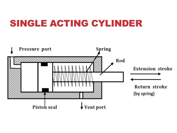
Oil Tube 14 4. Micro-Hydraulics Cylinders Compact High Force Micro-Hydraulics. When the fluid is supplied into the cylinder through pressure port.
Hydraulic Cylinder Parts Diagram Manufacture and Hydraulic Cylinder Parts Diagram Supplier in China DURATECH INDUSTRIAL GROUP LIMITED Hydraulic Cylinder Parts Diagram There are. The role of a pressure relief valve is to transfer fluids from areas of high pressures to those of low pressures. With the new micro-hydraulic cylinders high forces can be realized in a compact construction.
At the end of the brake line this hydraulic pressure is used by wheel cylinders to apply braking efforts on all wheels. O Ring 12 2. Using the drawing in Figure 27 the left portion of Figure 28 lists.
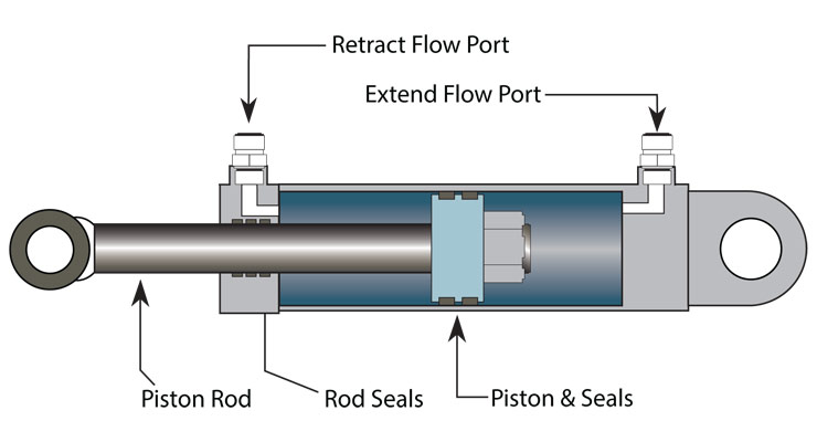
1 John Deere Hydraulic System Diagram with Parts Details. The hydraulic cylinder consists of a cylinder barrel in which a piston connected to a piston rod moves back and forth. 13 diagram of hydraulic cylinder Thursday October 27 2022 Rephasing also allows air to be purged.
Hydraulic system pictorial diagram. The barrel is closed on one end by the cylinder bottom also called the. Work is performed during forward motion as well as backward.
The position of the brake master cylinder in the braking system line. Hydraulic circuit for milling machine hitachi ex1200 5c a system balancing valve symbols ppt circuits. Figure 7 1 Hydraulic Lift System Schematic Diagram.
Elbow Fitting 13 3. Ad Get The Products You Need To Maintain Your Equipment At Optimal Performance. Ad Shop Zoro For Exclusive Offers on Millions of Everyday Products.
We carry Grizzly which includes Stock 2-stage hydraulic cylinders for ones log splitter tractor or other. Lock Nut 16 6. A simple diagram below helps explain the mechanics of the process -- as fluid enters a chamber more force is applied to push or pull the piston rod in or out of the cylinder.
Cutaway diagrams Figure 12-3 show the internal working parts of all fluid power components in a system. It consists of a piston which moves in a cylinder barrel and a piston rod is connected at one end. But before reading some complex examples lets look at a simple hydraulic system and convert it into a fluid power diagram.
Known For High Quality And Durability. Hydraulic Cylinders Cylinder Repair Kit Hydraulics Parts.
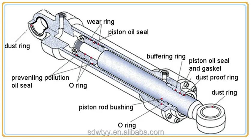
Hitachi Excavator Hydraulic Cylinder Buy Hitachi Excavator Hydraulic Cylinder Hitachi Excavator Hydraulic Cylinder Hitachi Excavator Hydraulic Cylinder Product On Alibaba Com
Hydraulic Cylinder Diagram Free Images At Clker Com Vector Clip Art Online Royalty Free Public Domain
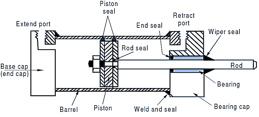
What Is Double Acting Hydraulic Cylinder Construction Diagram Working Electricalworkbook
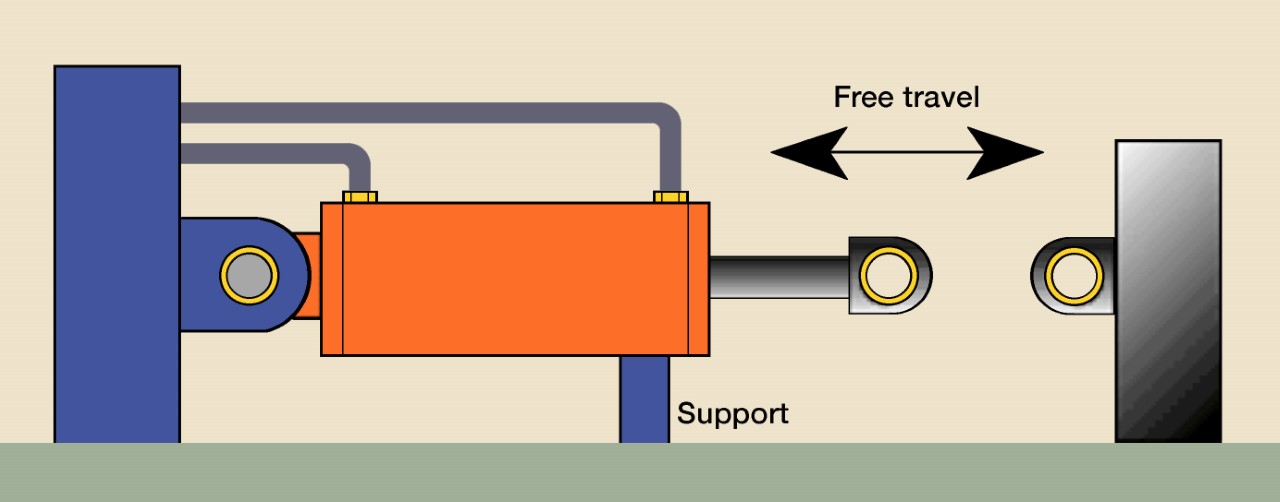
Bleeding Air From Hydraulic Cylinder

Hydraulic Circuit For Operating Double Acting Cylinder Using 4 3 Direction Control Valve Youtube
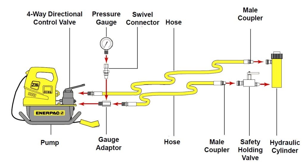
How To Set Up Your Single Or Multi Point Hydraulic System Enerpac Blog

Hydraulic Cylinder Drive
The Business End Of Hydraulics The Cylinder
2 Bore X 24 Stroke Hydraulic Cylinder Welded Tang Double Acting Cylinder Magister Hydraulics

Rigging Com A Toolwell Company Cylinders Part 4 How It Works
What Are Single Acting Double Acting Hydraulic Cylinders By Vcomp Inc Medium

Double Acting Cylinder Hfr2s Type Contarini
How Buffer Rod Seals Influence Rod Seal Performance Power Motion
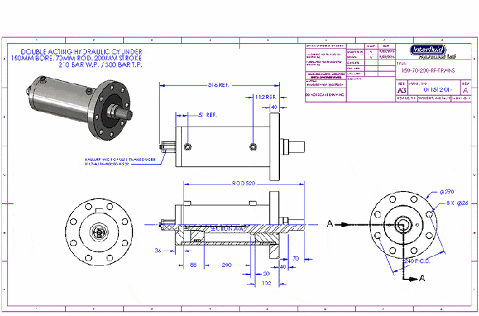
Hydraulic System Design Interfluid Hydraulics Ltd
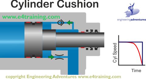
Hydraulic Cylinders
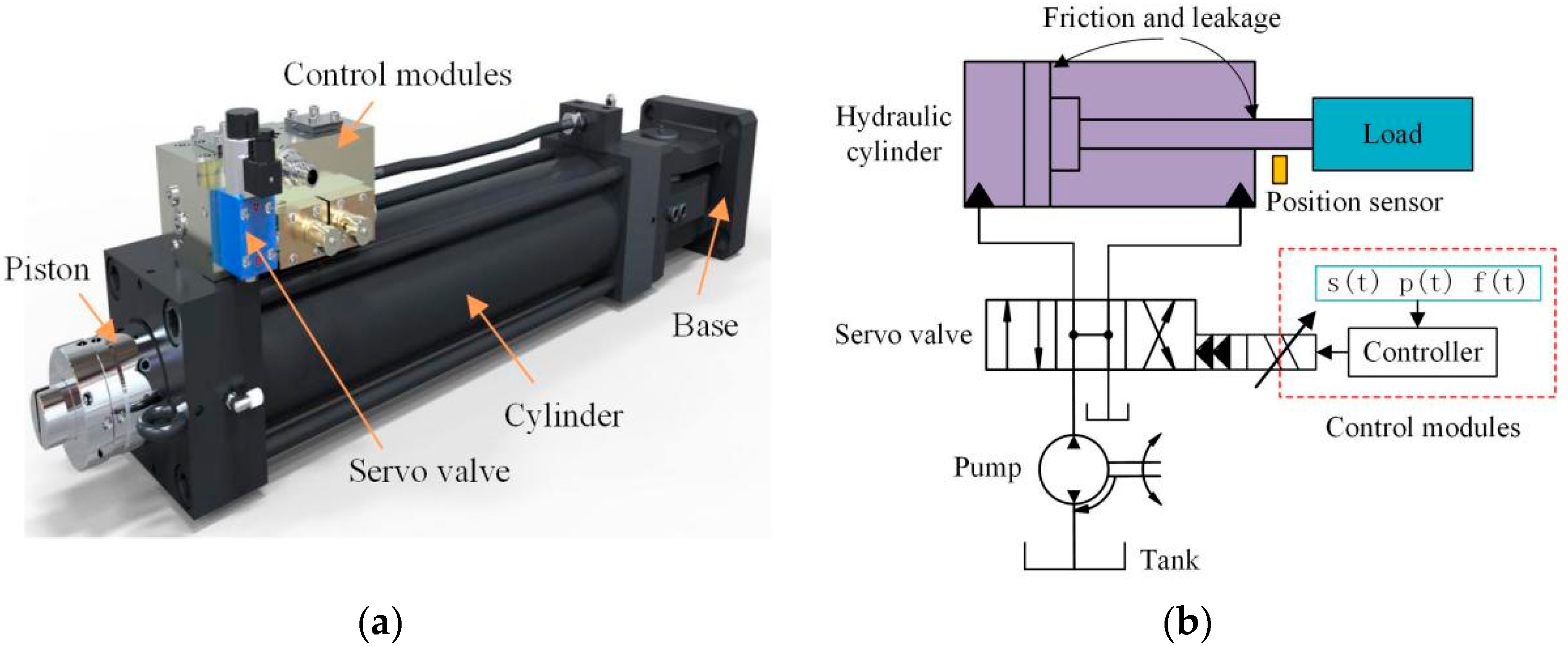
Applied Sciences Free Full Text Exploration And Research On Key Technologies For Improving The Response Speed Of Servo Hydraulic Cylinders Html
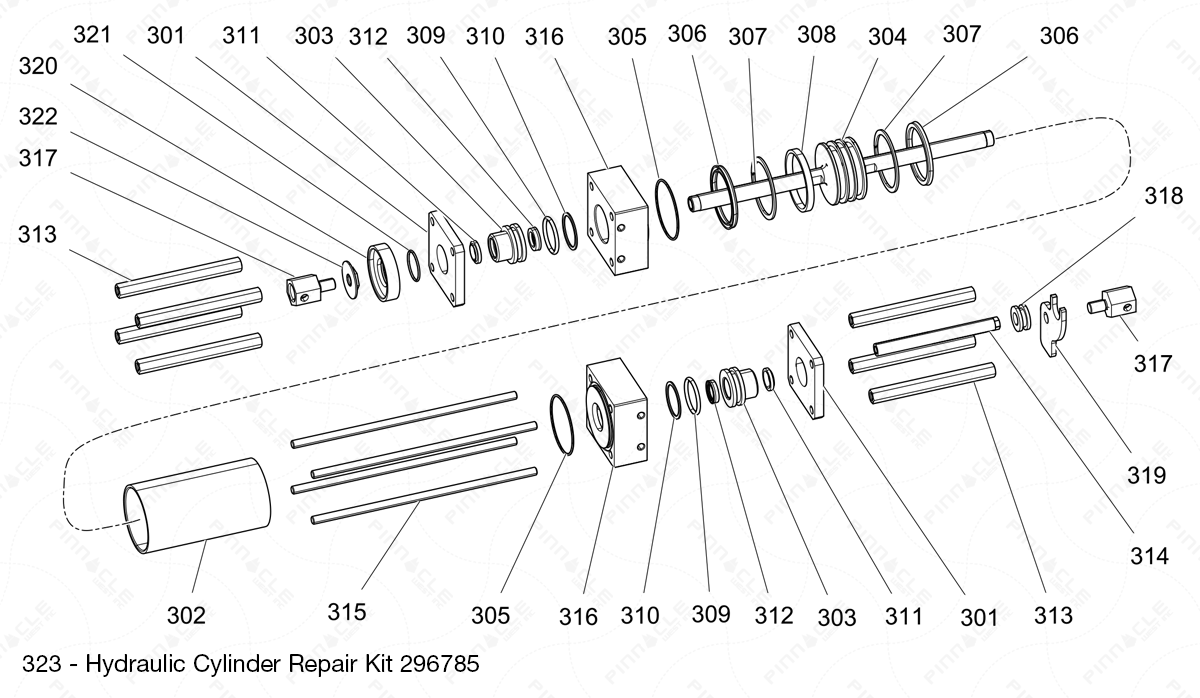
Reactor 2 H Series Hydraulic Cylinder Exploded Diagram Shop Online